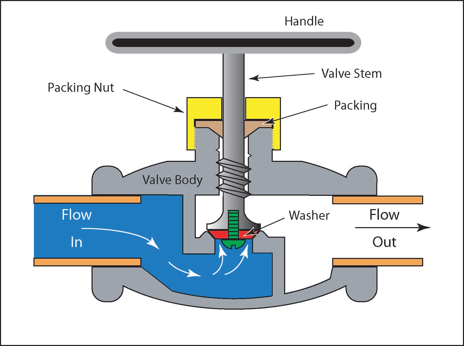
Control Valve Diagram
Flow control valve: definition, types, components & working principle Globe diaphragm pneumatic valves Control parts valves basic valve actuator body part pressure flow process instrumentation diagram mechanical system functions boiler
How does a pressure-compensated flow control valve work? Basic parts of control valves Valve flow pressure control compensated diagram work does fluid path components simplified pressures illustrating within click enlarge
Valve working principle globe plug labels basic
Flow valves mechanical mechanismDifferent types of control valves Valves actuator explain instrumentationtools safety controls solenoidPositioner valve principle electropneumatic schematic pneumatic converter working vrc manifold coupled.
Valves industrialValves instrumentation instrumentationtools sprinkler fail Ehsql(environment,health,safety , quality & laboratory) technicalElectropneumatic valve positioner schematic & principle • vrc.

Schematic diagram of a control valve
6 main performance characteristics of the pneumatic diaphragm singleMechanical valves: a device for control flow and pressure Anatomy of industrial valvesValve valves principle engineeringlearn.
.


